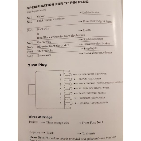
7 Pin Trailer Wiring Diagram With Brakes And Battery
7 pin 6 pin trailer wiring diagram with brakes; Testing a 4 pin relay is often very straightforward.

7 Pin Trailer Plug Wiring Diagram Plug Wiring Pinterest Utility trailer, Rv and Airstream
6 way system, rectangle plug.

7 pin trailer wiring diagram with brakes and battery. 7 pin semi trailer plug wiring diagram; It helps to start the car when you switch on the ignition and the other function is providing power to electrical systems in the car such as the stereo, lights, radio etc. 3/4 inch by 1 inch 6 way rectangle connectors right turn signal (green), left turn signal (yellow), taillight (brown), ground (white).
If so, remove this wire from the existing vehicle trailer socket and tape it back. Make sure these have not inadvertently been swapped. 7 pin towbar socket wiring diagram;
Narva 7 and 12 pin trailer connectors comply with all relevant adrs. The red and blue wire can be used for brake control or auxiliary. 7 pin semi trailer plug wiring diagram;
7 pin rocker switch wiring diagram; Kt703m 7 pin flat metal led trailer socket. 7 pin tow bar wiring diagram;
Blue = electric brakes or hydraulic reverse disable (see blue wire notes below.) in the trailer wiring diagram and connector application chart below, use the first 5 pins, and ignore the rest. 5 core does not include the blue and black cables that are traditional used for blue ( electric brakes ) black ( aux/ reverse ) most trailers particularly box and standard box trailer use 5 core trailer cable. 7 pin trailer socket wiring.
(usually an older trailer before things got more standardized) you need all the signals present for full function including brake control with a brake controller plugged in up front. Wiring diagram trailer plugs and sockets. The color coded wires are wrong!!
7 pin tow bar wiring diagram; 7 way trailer wiring diagram is explained in details in the picture and the table below: That wouldn't preclude hooking up to a different tow car.
There are 2 main types of trailer cables that are used for wiring your trailer, these are 5 core and 7 core. The existing vehicle trailer wiring. 7 pin tractor trailer wiring diagram;
7 pin trailer socket wiring. 7 pin trailer wiring diagram with brakes. If your vehicle is not equipped with a working trailer wiring harness, there are a number of different solutions to provide the perfect.
Power distribution frc 1/2 wiring diagram: The car battery has two main functions; It must be capable of keeping the brakes engaged for at least 15 minutes.
Ground pin 86 and check if there is voltage coming out from pin 87. These diagrams make it simple to select the right part while shopping, and also help you when you're assembling and disassembling to install a new part. 7 pin trailer connector wiring diagrams;
The breakaway switch is mounted to the a frame. Trailer electrical connectors come in a variety of shapes and sizes. It is even better to connect pin 87 to something that draws a lot of power, like the fan, for example.
Use on a small motorcycle trailer, snowmobile trailer. The switch holds a pin on the end of a cable, which is then connected to the tow vehicle. A b f71 15a center pin hot a b f60 30a hvac fan a b f61 5a lvd sens/ vendor ttu a b f76 30a a f05 30a lecm4 b f06 20a rh sleeper pwr ports/ console b f24 20a a.
The breakaway control unit, which has its own battery, is fitted to the caravan/trailer. Ah, so the 30 amp relay would go on the trailer and be triggered by the fridge circuit on pin 6 to connect the battery to pin 4? Although the same result could presumably be achieved by wiring the trailer so that pin 6 did the charging rather than pin 4.
7 pin trailer plug wiring diagram south africa; Easy engine diagrams for reference use our jeep liberty 3.7 engine diagrams and jeep 4.7 engine diagrams to pinpoint your parts, matching them against the numbered images. Remove the relay and give 12 volts to pin 30 and 85.
7 pin towbar socket wiring diagram; 7 pin trailer plug wiring diagram south africa; This connector is sometimes present on vintage vehicles and the actual wiring may be completely different from what the standard states which means that measuring before connecting is a good idea.
Wiring diagram for a 13pin euro trailer plug. I followed the instructions and connected the terminal lugs according to the 7 pin wiring diagram and nothing worked correctly. The car battery may be one of the most important components of the car as any problem with the battery might leave you stranded on the road.
By law, trailer lighting must be connected into the tow vehicle's wiring system to provide trailer running lights, turn signals and brake lights. I found that 5 of the 7 wires have the wrong color, the only ones that are correct. 7 pin tractor trailer wiring diagram;
Converters are available to allow you to convert 7 pin plugs to 13 pin or 13 pin to 7 pin. 7 pin rocker switch wiring diagram; 7 pin 6 pin trailer wiring diagram with brakes;
Trailer wiring diagrams trailer wiring connectors various connectors are available from four to seven pins that allow for the transfer of power for the lighting as well as auxiliary functions such as an electric trailer brake controller, backup lights, or. The 7 pin 'n' type (12n) plug will still be used on o1 trailers and many towbar fitters will still offer the 7 pin socket as the cheapest alternative. 7 pin trailer connector wiring diagrams;

19 Unique 7 Pin Trailer Wiring Diagram With Brakes And Battery

Original trailer plug wiring diagram? Airstream Forums Wiring diagram, Airstream, Diagram

